Since my previous posts about stand mixers and food processors, it seems like kitchen appliances is becoming my “thing”. I saw a Wilfa Svart coffee grinder being given away on a local share group. It wasn’t working and the owner had correctly identified that the cause of the fault was a failed capacitor, as documented in this post on coffee forums, but didn’t have the time or equipment to repair it, so instead gave it away. I’d already been thinking about getting a coffee grinder so I jumped on the opportunity. These units are popular for good reason – they seem to be well made (apart from the electronics) and the simple interface allows you to turn the bean hopper to set the grind coarseness, turn the knob to set the time to grind (so amount of coffee), and press the button to receive coffee.
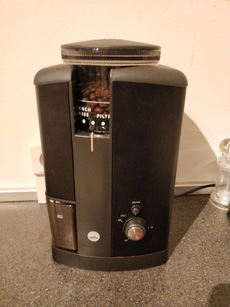
As per the prediction, the issue seemed to just be the one capacitor and once I exchanged it, the grinder worked again.
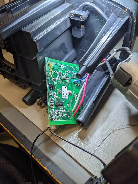
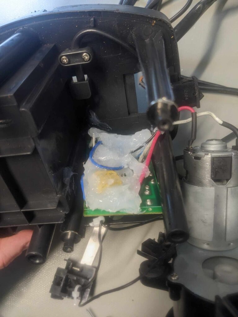
I unfortunately made a big mess in doing so, damaging the FR2 PCB and some components and having to repair it with wire mods. Optimistic that I’d never need to open it again, I gunked it up with some silicone to hide my sins.
All was well for a while, and I also got lucky and found 6 more grinders in the trash outside my office.
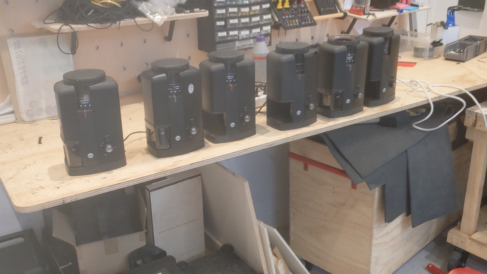
Three of these seemed to have the same fault as the first one I got: making strange noises or stopping prematurely. Another one seemed to grind constantly when power was applied and another two seemed to work fine. At about the same time, the first one I modified was starting to play up – making strange noises again like with the capacitor fault. This got me curious about the circuitry so I set about reverse engineering it.
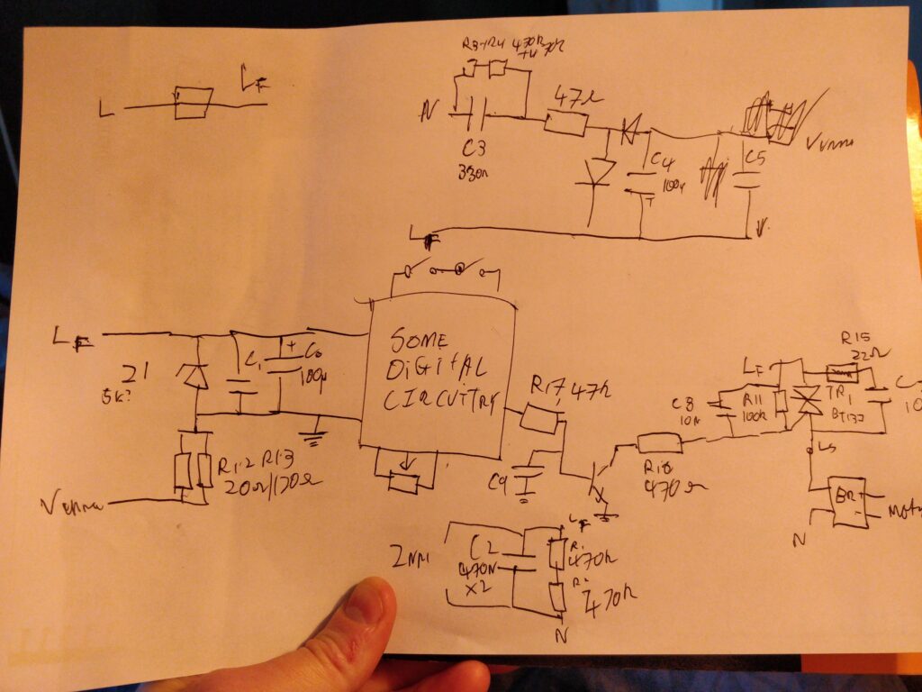
This schematic isn’t very readable but in reverse engineering it I discovered two interesting things:
- The DC motor is, strangely, powered through a bridge rectifier switched by a TRIAC. It seems like a strange choice to switch a DC motor using a DC signal, but use a TRIAC on the AC side. I’d have expected a MOSFET to be used instead. Perhaps this was done for cost reasons?
- The digital circuitry is supplied through a capacitive dropper – the capacitor which is known to fail.
The latter seemed like a poor design choice to me. It’s very common to see safety capacitors used in a capacitive dropper like this, but it isn’t generally a recommended use for these types. Vishay have an application note on the various uses for safety capacitors, with a specific recommendation for a range which is suitable for use in series with the mains like this – illustrating that not all such capacitors are suitable for this application. I’m not entirely sure of the reason for their unsuitability but I suspect it’s related to their self-healing, which depends on enough current being available to burn through the metallisation and contain short circuits when the dielectric fails.
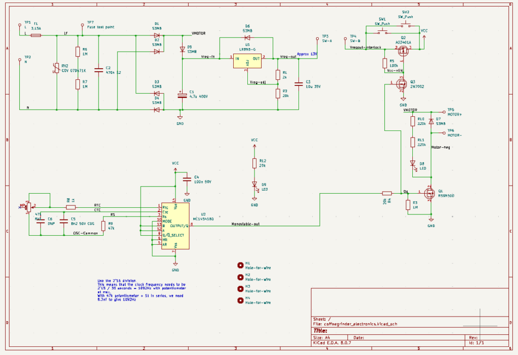
I put together a design for a complete replacement for the electronics in KiCAD. To summarise the key design decisions:
- The input protection, consisting of a fuse, MOV and a safety capacitor are copied directly from the original. I’m not an expert in electrical safety and nor do I have the equipment to test emissions so I decided not to touch this. I figured nothing else I was changing would have any significant effect on these.
- The timing is done by an MC14541BD. The capacitor is chosen to give the same maximum time (30s) as the original, with a minimum of around 1 second.
- The potentiometer is reused from the original. Apart from this, the circuit uses all new electronic components with nothing being scavenged from the original. But I wasn’t able to find a potentiometer with the same mounting hardware. If anyone else fancies having a go, the original is around 47-50kohm.
- The timing circuit has a power-on reset. When the button is pressed, the MC14541BD powers up and produces one pulse. While the output is high, the motor is switched on with a MOSFET. Another pair of MOSFETs bypass the switch to continue to provide power to the timer.
- The DC power supply is produced using an LR8 regulator: a linear regulator suitable for input voltages up to 450V. It has a minimum load of 500uA to maintain regulation, and the potential divider I chose consumes 600uA. This makes up all of the standby power consumption of the device: around 600uA at 300VDC, or around 0.18W, which corresponds to about 1.5kWh per year.
- Electrolytic capacitors can be the limiting factor in a circuit’s lifetime, so where I had to use one, I used a rubycon one rather than an unknown brand
I measured up the original PCB, including the location of the potentiometer and tactile switch, and made a very quick and dirty layout. I noticed that the original PCB seemed to have a copper keepout at the bottom and top of the PCB. I assumed this was related so some kind of safety/double insulation requirement so kept this the same in mine.
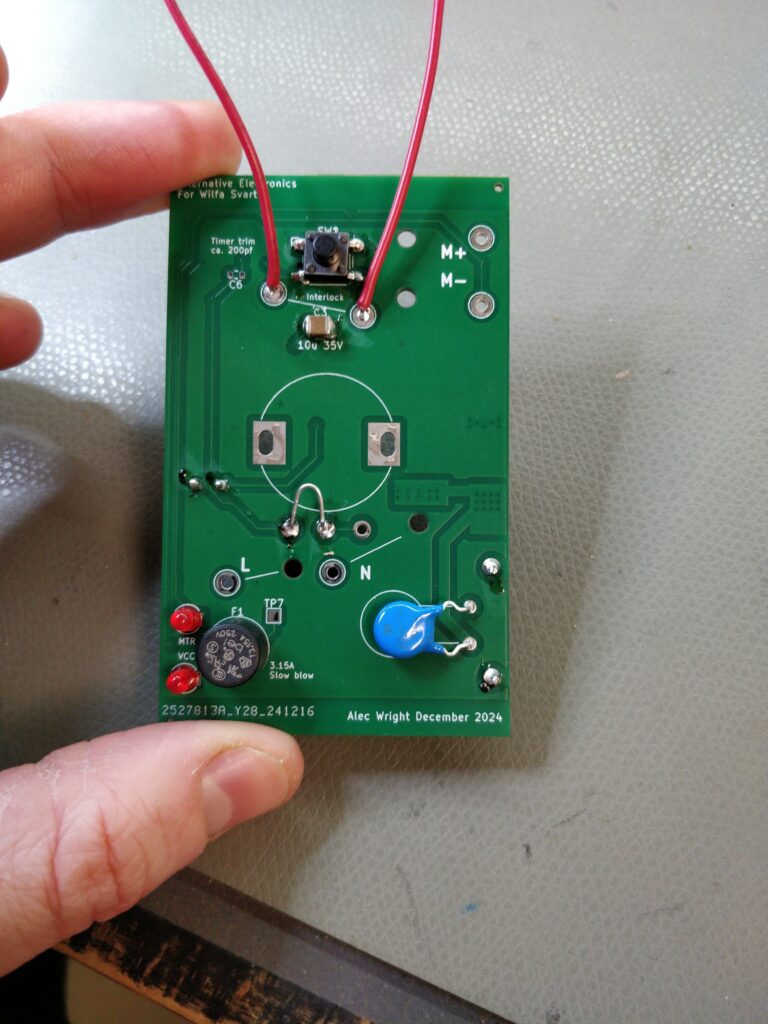
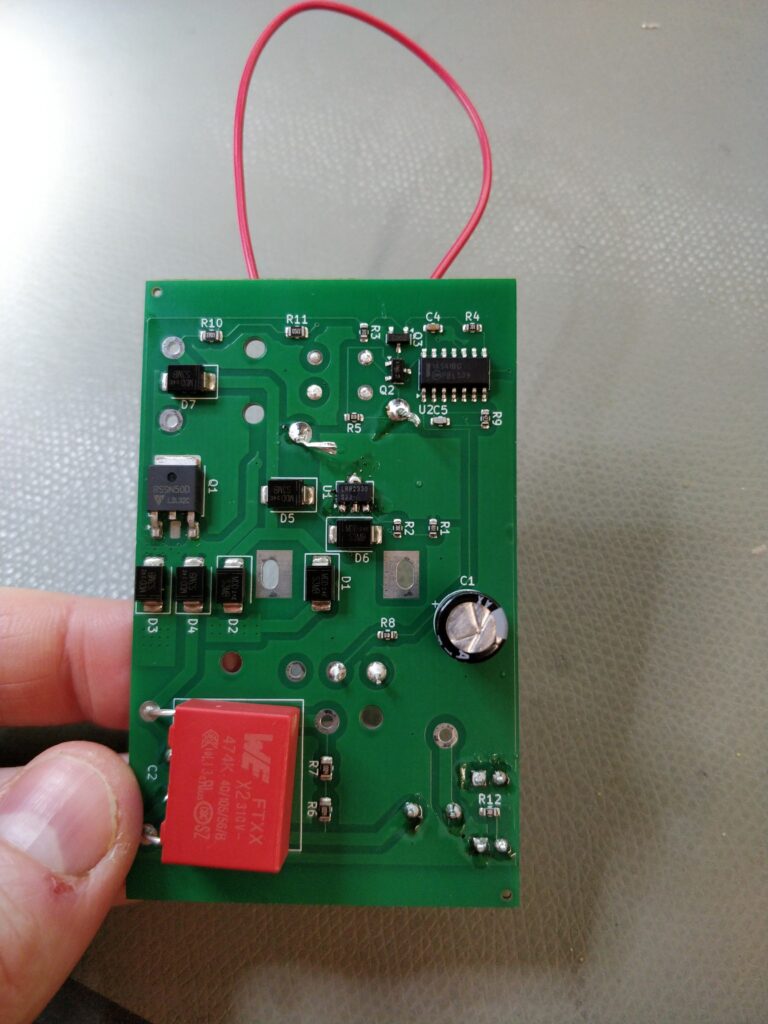
Here is the circuit soldered up, except for the potentiometer and interlock switches which are bypassed for testing. The quality of the soldering betrays the fact that I’m a design engineer and not an assembly technician but luckily this caused no problems. On the first test I could see that there was one issue though: when the button is pressed the circuit switches on, but it never switches off again. If I watched closely, I could see the motor LED flash off briefly about once per second.
I connected up just the low voltage side to a bench power supply and saw the problem: the power-on reset of the MC14541BD also triggers on power off.
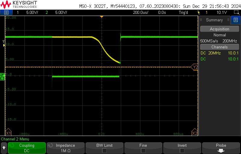
Here, yellow shows the power supply pin of the MC14541BD and the green shows the output. When the timer runs out, the output immediately goes low, which switches off the MOSFET providing power. After a few hundred microseconds, the power supply rail falls. When it reaches around 4-5V, the power-on reset triggers, resets the timer and switches the MOSFET back on. It gets stuck in this loop which it can never leave. To me, this is incorrect behaviour of a power-on reset: it should have a hysteresis and only trigger on a rising edge of the supply voltage. Nonetheless I found a solution.
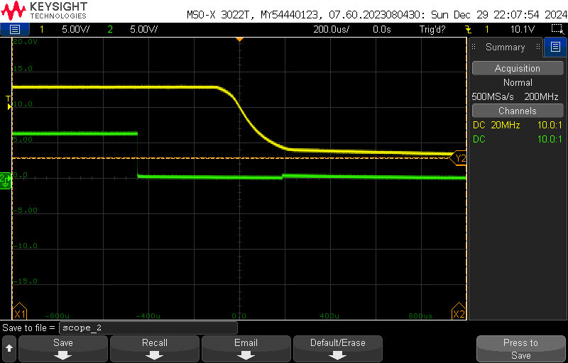
I replaced the series resistor with a 6V8 zener: this gives enough voltage on the gate to switch on the MOSFETs when the supply is fully up, but prevents it from activating the MOSFET when the supply is low. Here the yellow trace again shows the power supply, but the green line shows the MOSFET Vgs. You can see that, as before, the IC tried to switch the MOSFET again, but isn’t able to reach the threshold voltage because of the zener. In fact, I improved this further by changing the pull-down resistor from 1M to 10k. After this, there was no visible change in the gate voltage when the timer resets.
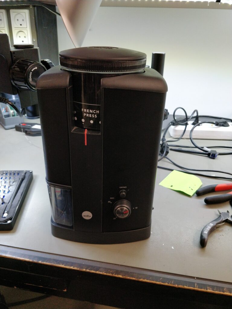
And with that, we have a working coffee grinder! I added the zener and replace the resistor on the 10 boards I got made:
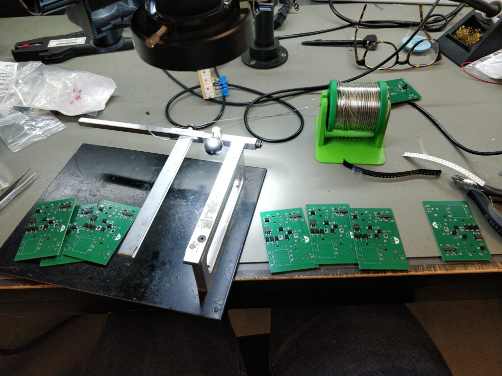
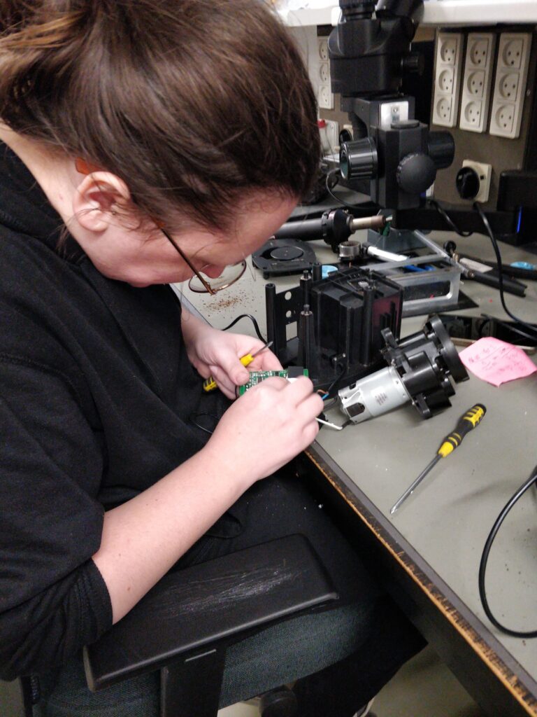
And even got my partner to replace the board in one of the broken grinders:
All that remains is to do a bit of a clean-up. When I found these 6 grinders in the trash, I asked around several of my friends to see if they wanted one. Most of them said that they already had this exact model of grinder! It’s clearly a popular model so I figured some folk reading this might want to follow in my footsteps – in which case it makes sense for me to do the small updates which are needed for the design. The changes were:
- The zener diode modification described above
- It turned out that the motor wires were a bit thicker than the 2.5mm holes I used, so I expanded these to 3.5mm
- The 2012 capacitor on the output of the LR8 regulator was a bit tricky to hand solder. I changed the footprint to one with larger pads for hand soldering
- The push button footprint was a bit too narrow. I widened the pads a little
- Moved the LR8 up a little to give more room for soldering
- Increased the LR8 output voltage a little and increased the zener voltage to 9V1 to give a bit more margin against the unknown variation in the timer’s power-on-reset threshold without affecting the gate voltage on the MOSFETs in normal operation
And here are the kicad design file and gerbers. The gerbers are ready to be uploaded to JLCPCB, and you can add assembly of the bottom side with a little bit of manual placement.
Let me know if this is useful to you! Comment on here or send me an email on alec@nothinguntoward.eu. Since I know a few people who use this grinder, I might get a few more of these PCBs made, so if you’re lucky and you email me, I might be able to spare one. Good luck to anyone else following along at home!